| ORBITAL MECHANICS |
- Conic Sections
- Orbital Elements
- Types of Orbits
- Newton's Laws of Motion and Universal Gravitation
- Uniform Circular Motion
- Motions of Planets and Satellites
- Launch of a Space Vehicle
- Position in an Elliptical Orbit
- Orbit Perturbations
- Orbit Maneuvers
- The Hyperbolic Orbit
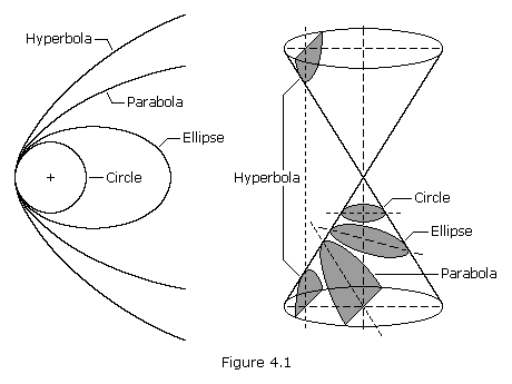
A conic section, or just conic, is a curve formed by
passing a plane through a right circular cone. As shown in Figure 4.1,
the angular orientation of the plane relative to the cone determines
whether the conic section is a circle, ellipse, parabola, or hyperbola.
The circle and the ellipse arise when the intersection of cone and
plane is a bounded curve. The circle is a special case of the ellipse in
which the plane is perpendicular to the axis of the cone. If the plane
is parallel to a generator line of the cone, the conic is called a
parabola. Finally, if the intersection is an unbounded curve and the
plane is not parallel to a generator line of the cone, the figure is a
hyperbola. In the latter case the plane will intersect both halves of
the cone, producing two separate curves.
We can define all conic sections in terms of the eccentricity.
The type of conic section is also related to the semi-major axis and the
energy. The table below shows the relationships between eccentricity,
semi-major axis, and energy and the type of conic section.
| Conic Section | Eccentricity, e | Semi-major axis | Energy |
|---|---|---|---|
| Circle | 0 | = radius | < 0 |
| Ellipse | 0 < e < 1 | > 0 | < 0 |
| Parabola | 1 | infinity | 0 |
| Hyperbola | > 1 | < 0 | > 0 |
Satellite orbits can be any of the four conic sections. This page
deals mostly with elliptical orbits, though we conclude with an
examination of the hyperbolic orbit.
To mathematically describe an orbit one must define six quantities, called orbital elements. They are
- Semi-Major Axis, a
- Eccentricity, e
- Inclination, i
- Argument of Periapsis,

- Time of Periapsis Passage, T
- Longitude of Ascending Node,

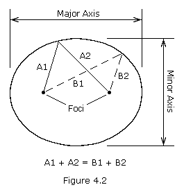
An orbiting satellite follows an oval shaped path known as an ellipse
with the body being orbited, called the primary, located at one of two
points called foci. An ellipse is defined to be a curve with the
following property: for each point on an ellipse, the sum of its
distances from two fixed points, called foci, is constant (see Figure
4.2). The longest and shortest lines that can be drawn through the
center of an ellipse are called the major axis and minor axis,
respectively. The semi-major axis is one-half of the major axis and represents a satellite's mean distance from its primary. Eccentricity
is the distance between the foci divided by the length of the major
axis and is a number between zero and one. An eccentricity of zero
indicates a circle.
Inclination is the angular distance between a satellite's
orbital plane and the equator of its primary (or the ecliptic plane in
the case of heliocentric, or sun centered, orbits). An inclination of
zero degrees indicates an orbit about the primary's equator in the same
direction as the primary's rotation, a direction called prograde
(or direct). An inclination of 90 degrees indicates a polar orbit. An
inclination of 180 degrees indicates a retrograde equatorial orbit. A retrograde orbit is one in which a satellite moves in a direction opposite to the rotation of its primary.
Periapsis is the point in an orbit closest to the primary. The opposite of periapsis, the farthest point in an orbit, is called apoapsis.
Periapsis and apoapsis are usually modified to apply to the body being
orbited, such as perihelion and aphelion for the Sun, perigee and apogee
for Earth, perijove and apojove for Jupiter, perilune and apolune for
the Moon, etc. The argument of periapsis is the angular distance between the ascending node and the point of periapsis (see Figure 4.3). The time of periapsis passage is the time in which a satellite moves through its point of periapsis.
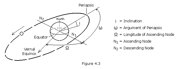 Nodes are the points where an orbit crosses a plane, such as a
satellite crossing the Earth's equatorial plane. If the satellite
crosses the plane going from south to north, the node is the ascending node; if moving from north to south, it is the descending node. The longitude of the ascending node
is the node's celestial longitude. Celestial longitude is analogous to
longitude on Earth and is measured in degrees counter-clockwise from
zero with zero longitude being in the direction of the vernal equinox.
In general, three observations of an object in orbit are required to
calculate the six orbital elements. Two other quantities often used to
describe orbits are period and true anomaly. Period, P, is the length of time required for a satellite to complete one orbit. True anomaly,  , is the angular distance of a point in an orbit past the point of periapsis, measured in degrees.
For a spacecraft to achieve Earth orbit, it must be launched to an
elevation above the Earth's atmosphere and accelerated to orbital
velocity. The most energy efficient orbit, that is one that requires
the least amount of propellant, is a direct low inclination orbit. To
achieve such an orbit, a spacecraft is launched in an eastward direction
from a site near the Earth's equator. The advantage being that the
rotational speed of the Earth contributes to the spacecraft's final
orbital speed. At the United States' launch site in Cape Canaveral (28.5
degrees north latitude) a due east launch results in a "free ride" of
1,471 km/h (914 mph). Launching a spacecraft in a direction other than
east, or from a site far from the equator, results in an orbit of higher
inclination. High inclination orbits are less able to take advantage of
the initial speed provided by the Earth's rotation, thus the launch
vehicle must provide a greater part, or all, of the energy required to
attain orbital velocity. Although high inclination orbits are less
energy efficient, they do have advantages over equatorial orbits for
certain applications. Below we describe several types of orbits and the
advantages of each:
Geosynchronous orbits (GEO) are circular orbits
around the Earth having a period of 24 hours. A geosynchronous orbit
with an inclination of zero degrees is called a geostationary orbit.
A spacecraft in a geostationary orbit appears to hang motionless above
one position on the Earth's equator. For this reason, they are ideal for
some types of communication and meteorological satellites. A spacecraft
in an inclined geosynchronous orbit will appear to follow a regular
figure-8 pattern in the sky once every orbit. To attain geosynchronous
orbit, a spacecraft is first launched into an elliptical orbit with an
apogee of 35,786 km (22,236 miles) called a geosynchronous transfer orbit (GTO). The orbit is then circularized by firing the spacecraft's engine at apogee.
Polar orbits (PO) are orbits with an inclination of
90 degrees. Polar orbits are useful for satellites that carry out
mapping and/or surveillance operations because as the planet rotates the
spacecraft has access to virtually every point on the planet's surface.
Walking orbits: An orbiting satellite is subjected
to a great many gravitational influences. First, planets are not
perfectly spherical and they have slightly uneven mass distribution.
These fluctuations have an effect on a spacecraft's trajectory. Also,
the sun, moon, and planets contribute a gravitational influence on an
orbiting satellite. With proper planning it is possible to design an
orbit which takes advantage of these influences to induce a precession
in the satellite's orbital plane. The resulting orbit is called a walking orbit, or precessing orbit.
Sun synchronous orbits (SSO) are walking orbits
whose orbital plane precesses with the same period as the planet's solar
orbit period. In such an orbit, a satellite crosses periapsis at about
the same local time every orbit. This is useful if a satellite is
carrying instruments which depend on a certain angle of solar
illumination on the planet's surface. In order to maintain an exact
synchronous timing, it may be necessary to conduct occasional propulsive
maneuvers to adjust the orbit.
Molniya orbits are highly eccentric Earth orbits
with periods of approximately 12 hours (2 revolutions per day). The
orbital inclination is chosen so the rate of change of perigee is zero,
thus both apogee and perigee can be maintained over fixed latitudes.
This condition occurs at inclinations of 63.4 degrees and 116.6 degrees.
For these orbits the argument of perigee is typically placed in the
southern hemisphere, so the satellite remains above the northern
hemisphere near apogee for approximately 11 hours per orbit. This
orientation can provide good ground coverage at high northern latitudes.
Hohmann transfer orbits are interplanetary
trajectories whose advantage is that they consume the least possible
amount of propellant. A Hohmann transfer orbit to an outer planet, such
as Mars, is achieved by launching a spacecraft and accelerating it in
the direction of Earth's revolution around the sun until it breaks free
of the Earth's gravity and reaches a velocity which places it in a sun
orbit with an aphelion equal to the orbit of the outer planet. Upon
reaching its destination, the spacecraft must decelerate so that the
planet's gravity can capture it into a planetary orbit.
To send a spacecraft to an inner planet, such as Venus, the
spacecraft is launched and accelerated in the direction opposite of
Earth's revolution around the sun (i.e. decelerated) until it achieves a
sun orbit with a perihelion equal to the orbit of the inner planet. It
should be noted that the spacecraft continues to move in the same
direction as Earth, only more slowly.
To reach a planet requires that the spacecraft be inserted into
an interplanetary trajectory at the correct time so that the spacecraft
arrives at the planet's orbit when the planet will be at the point where
the spacecraft will intercept it. This task is comparable to a
quarterback "leading" his receiver so that the football and receiver
arrive at the same point at the same time. The interval of time in which
a spacecraft must be launched in order to complete its mission is
called a launch window.
Newton's laws of motion describe the relationship between the motion of a particle and the forces acting on it.
The first law states that if no forces are acting, a body at rest
will remain at rest, and a body in motion will remain in motion in a
straight line. Thus, if no forces are acting, the velocity (both
magnitude and direction) will remain constant.
The second law tells us that if a force is applied there will be a
change in velocity, i.e. an acceleration, proportional to the magnitude
of the force and in the direction in which the force is applied. This
law may be summarized by the equation
where F is the force, m is the mass of the particle, and a is the acceleration.
The third law states that if body 1 exerts a force on body 2,
then body 2 will exert a force of equal strength, but opposite in
direction, on body 1. This law is commonly stated, "for every action
there is an equal and opposite reaction".
In his law of universal gravitation, Newton states that two particles having masses m1 and m2 and separated by a distance r are attracted to each other with equal and opposite forces directed along the line joining the particles. The common magnitude F of the two forces is
where G is an universal constant, called the constant of gravitation, and has the value 6.67259x10⁻¹¹ N-m2/kg2 (3.4389x10⁻⁸ lb-ft2/slug2).
Let's now look at the force that the Earth exerts on an object. If the object has a mass m, and the Earth has mass M, and the object's distance from the center of the Earth is r, then the force that the Earth exerts on the object is GmM /r2 .
If we drop the object, the Earth's gravity will cause it to accelerate
toward the center of the Earth. By Newton's second law (F = ma), this
acceleration g must equal (GmM /r2)/m, or
At the surface of the Earth this acceleration has the valve 9.80665 m/s2 (32.174 ft/s2).
Many of the upcoming computations will be somewhat simplified if we express the product GM as a constant, which for Earth has the value 3.986005x10¹⁴ m3/s2 (1.408x1016 ft3/s2). The product GM is often represented by the Greek letter  .
.
For a refresher on SI versus U.S. units see the appendix Weights & Measures.
In the simple case of free fall, a particle accelerates toward the
center of the Earth while moving in a straight line. The velocity of the
particle changes in magnitude, but not in direction. In the case of
uniform circular motion a particle moves in a circle with constant
speed. The velocity of the particle changes continuously in direction,
but not in magnitude. From Newton's laws we see that since the direction
of the velocity is changing, there is an acceleration. This
acceleration, called centripetal acceleration is directed inward toward the center of the circle and is given by
where v is the speed of the particle and r is the
radius of the circle. Every accelerating particle must have a force
acting on it, defined by Newton's second law (F = ma). Thus, a particle
undergoing uniform circular motion is under the influence of a force,
called centripetal force, whose magnitude is given by
The direction of F at any instant must be in the direction of a at the same instant, that is radially inward.
A satellite in orbit is acted on only by the forces of gravity.
The inward acceleration which causes the satellite to move in a circular
orbit is the gravitational acceleration caused by the body around which
the satellite orbits. Hence, the satellite's centripetal acceleration
is g, that is g = v2/r. From Newton's law of universal gravitation we know that g = GM /r2. Therefore, by setting these equations equal to one another we find that, for a circular orbit,

Click here for example problem #4.1
(use your browser's "back" function to return)
Through a lifelong study of the motions of bodies in the solar
system, Johannes Kepler (1571-1630) was able to derive three basic laws
known as Kepler's laws of planetary motion. Using the data
compiled by his mentor Tycho Brahe (1546-1601), Kepler found the
following regularities after years of laborious calculations:
1. All planets move in elliptical orbits with the sun at one focus.
2. A line joining any planet to the sun sweeps out equal areas in equal times.
3. The square of the period of any planet about the sun is proportional to the cube of the planet's mean distance from the sun.
These laws can be deduced from Newton's laws of motion and law of
universal gravitation. Indeed, Newton used Kepler's work as basic
information in the formulation of his gravitational theory.
As Kepler pointed out, all planets move in elliptical orbits,
however, we can learn much about planetary motion by considering the
special case of circular orbits. We shall neglect the forces between
planets, considering only a planet's interaction with the sun. These
considerations apply equally well to the motion of a satellite about a
planet.
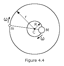
Let's examine the case of two bodies of masses M and m
moving in circular orbits under the influence of each other's
gravitational attraction. The center of mass of this system of two
bodies lies along the line joining them at a point C such that mr = MR. The large body of mass M moves in an orbit of constant radius R and the small body of mass m in an orbit of constant radius r, both having the same angular velocity  .
For this to happen, the gravitational force acting on each body must
provide the necessary centripetal acceleration. Since these
gravitational forces are a simple action-reaction pair, the centripetal
forces must be equal but opposite in direction. That is, m
 2r must equal M
 2R.
The specific requirement, then, is that the gravitational force acting
on either body must equal the centripetal force needed to keep it moving
in its circular orbit, that is
If one body has a much greater mass than the other, as is the case of
the sun and a planet or the Earth and a satellite, its distance from
the center of mass is much smaller than that of the other body. If we
assume that m is negligible compared to M, then R is negligible compared to r. Thus, equation (4.7) then becomes
If we express the angular velocity in terms of the period of revolution,  = 2
= 2 /P, we obtain

where P is the period of revolution. This is a basic equation
of planetary and satellite motion. It also holds for elliptical orbits
if we define r to be the semi-major axis (a) of the orbit.
A significant consequence of this equation is that it predicts Kepler's third law of planetary motion, that is P2~r3.
Click here for example problem #4.2
Click here for example problem #4.3
| In
celestial mechanics where we are dealing with planetary or stellar
sized bodies, it is often the case that the mass of the secondary body
is significant in relation to the mass of the primary, as with the Moon
and Earth. In this case the size of the secondary cannot be ignored.
The distance R is no longer negligible compared to r and, therefore, must be carried through the derivation. Equation (4.9) becomes
More commonly the equation is written in the equivalent form where a is the semi-major axis. The semi-major axis used in astronomy is always the primary-to-secondary distance, or the geocentric semi-major axis. For example, the Moon's mean geocentric distance from Earth (a) is 384,403 kilometers. On the other hand, the Moon's distance from the barycenter (r) is 379,732 km, with Earth's counter-orbit (R) taking up the difference of 4,671 km. |
Kepler's second law of planetary motion must, of course, hold true for circular orbits. In such orbits both  and r
are constant so that equal areas are swept out in equal times by the
line joining a planet and the sun. For elliptical orbits, however, both
  and r will vary with time. Let's now consider this case.
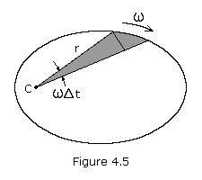
Figure 4.5 shows a particle revolving around C along some arbitrary path. The area swept out by the radius vector in a short time interval  t
is shown shaded. This area, neglecting the small triangular region at
the end, is one-half the base times the height or approximately r(r
t
is shown shaded. This area, neglecting the small triangular region at
the end, is one-half the base times the height or approximately r(r
 t)/2. This expression becomes more exact as
  t
approaches zero, i.e. the small triangle goes to zero more rapidly than
the large one. The rate at which area is being swept out
instantaneously is therefore
t
approaches zero, i.e. the small triangle goes to zero more rapidly than
the large one. The rate at which area is being swept out
instantaneously is therefore
For any given body moving under the influence of a central force, the value  r2 is constant.
Let's now consider two points P1 and P2 in an orbit with radii r1 and r2, and velocities v1 and v2. Since the velocity is always tangent to the path, it can be seen that if  is the angle between r and v, then
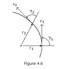
where vsin is the transverse component of v. Multiplying through by r, we have
or, for two points P1 and P2 on the orbital path
Note that at periapsis and apoapsis,  = 90 degrees. Thus, letting P1 and P2 be these two points we get
Let's now look at the energy of the above particle at points P1 and P2. Conservation of energy states that the sum of the kinetic energy and the potential energy of a particle remains constant. The kinetic energy T of a particle is given by mv2/2 while the potential energy of gravity V is calculated by the equation -GMm/r. Applying conservation of energy we have
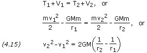
From equations (4.14) and (4.15) we obtain

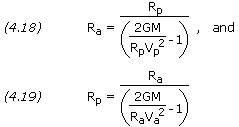
Rearranging terms we get
Click here for example problem #4.4
Click here for example problem #4.5
The eccentricity e of an orbit is given by
If the semi-major axis a and the eccentricity e of an orbit are known, then the periapsis and apoapsis distances can be calculated by

The launch of a satellite or space vehicle consists of a period of
powered flight during which the vehicle is lifted above the Earth's
atmosphere and accelerated to orbital velocity by a rocket, or launch
vehicle. Powered flight concludes at burnout of the rocket's last stage
at which time the vehicle begins its free flight. During free flight
the space vehicle is assumed to be subjected only to the gravitational
pull of the Earth. If the vehicle moves far from the Earth, its
trajectory may be affected by the gravitational influence of the sun,
moon, or another planet.
A space vehicle's orbit may be determined from the position and
the velocity of the vehicle at the beginning of its free flight. A
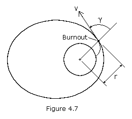
vehicle's position and velocity can be described by the variables r, v, and  , where r is the vehicle's distance from the center of the Earth, v is its velocity, and
  is the angle between the position and the velocity vectors, called the zenith angle (see Figure 4.7). If we let r1, v1, and
  1 be the initial (launch) values of r, v, and
  , then we may consider these as given quantities. If we let point P2 represent the perigee, then equation (4.13) becomes
Substituting equation (4.23) into (4.15), we can obtain an equation for the perigee radius Rp.
Multiplying through by -Rp2/(r12v12) and rearranging, we get

Note that this is a simple quadratic equation in the ratio (Rp/r1) and that 2GM /(r1 × v12) is a nondimensional parameter of the orbit.
Solving for (Rp/r1) gives
Like any quadratic, the above equation yields two answers. The smaller of the two answers corresponds to Rp, the periapsis radius. The other root corresponds to the apoapsis radius, Ra.
Please note that in practice spacecraft launches are usually terminated at either perigee or apogee, i.e.  = 90. This condition results in the minimum use of propellant.
Equation (4.26) gives the values of Rp and Ra from which the eccentricity of the orbit can be calculated, however, it may be simpler to calculate the eccentricity e directly from the equation
To pin down a satellite's orbit in space, we need to know the angle  , the true anomaly, from the periapsis point to the launch point. This angle is given by

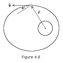
In most calculations, the complement of the zenith angle is used, denoted by  . This angle is called the flight-path angle,
and is positive when the velocity vector is directed away from the
primary as shown in Figure 4.8. When flight-path angle is used,
equations (4.26) through (4.28) are rewritten as follows:
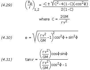
The semi-major axis is, of course, equal to (Rp+Ra)/2, though it may be easier to calculate it directly as follows:

If e is solved for directly using equation (4.27) or (4.30), and a is solved for using equation (4.32), Rp and Ra can be solved for simply using equations (4.21) and (4.22).
Orbit Tilt, Rotation and Orientation
Above we determined the size and shape of the orbit, but to
determine the orientation of the orbit in space, we must know the
latitude and longitude and the heading of the space vehicle at burnout.
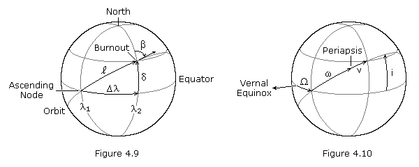
Figure 4.9 above illustrates the location of a space vehicle at engine burnout, or orbit insertion.  is the azimuth heading measured in degrees clockwise from north,
  is the geocentric latitude (or declination) of the burnout point,
 is the angular distance between the ascending node and the burnout point measured in the equatorial plane, and
  is the angular distance between the ascending node and the burnout point measured in the orbital plane.
  1 and
1 and  2
are the geographical longitudes of the ascending node and the burnout
point at the instant of engine burnout. Figure 4.10 pictures the orbital
elements, where i is the inclination,
  is the longitude at the ascending node,
  is the argument of periapsis, and
  is the true anomaly.
If  ,
,  , and
, and  2 are given, the other values can be calculated from the following relationships:
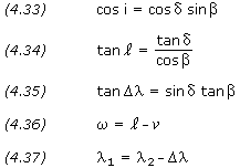
In equation (4.36), the value of  is found using equation (4.28) or (4.31). If
  is positive, periapsis is west of the burnout point (as shown in Figure 4.10); if
  is negative, periapsis is east of the burnout point.
The longitude of the ascending node,  , is measured in celestial longitude, while
  1 is geographical longitude. The celestial longitude of the ascending node is equal to the local apparent sidereal time, in degrees, at longitude
  1
at the time of engine burnout. Sidereal time is defined as the hour
angle of the vernal equinox at a specific locality and time; it has the
same value as the right ascension of any celestial body that is crossing
the local meridian at that same instant. At the moment when the vernal
equinox crosses the local meridian, the local apparent sidereal time is
00:00. See this sidereal time calculator.
Geodetic Latitude, Geocentric Latitude, and Declination
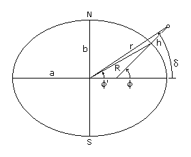 Latitude is the angular distance of a point on Earth's surface north or
south of Earth's equator, positive north and negative south. The geodetic latitude (or geographical latitude),
 R is the magnitude of the reference ellipsoid's geocentric radius vector to the point of interest on its surface, r is the magnitude of the geocentric radius vector to the celestial object of interest, and the altitude h is the perpendicular distance from the reference ellipsoid to the celestial object of interest. The value of R at the equator is a, and the value of R at the poles is b. The ellipsoid's flattening, f, is the ratio of the equatorial-polar length difference to the equatorial length. For Earth, a equals 6,378,137 meters, b equals 6,356,752 meters, and f equals 1/298.257. When solving problems in orbital mechanics, the measurements of greatest usefulness are the magnitude of the radius vector, r, and declination, The relationship between geodetic and geocentric latitude is, The radius of the reference ellipsoid is given by, The length r can be solved from h, or h from r, using one of the following,  And declination is calculated using, For spacecraft in low earth orbit, the difference between |
where Mo is the mean anomaly at time to and n is the mean motion, or the average angular velocity, determined from the semi-major axis of the orbit as follows:
This solution will give the average position and velocity, but
satellite orbits are elliptical with a radius constantly varying in
orbit. Because the satellite's velocity depends on this varying radius,
it changes as well. To resolve this problem we can define an
intermediate variable E, called the eccentric anomaly, for elliptical orbits, which is given by
where  is the true anomaly. Mean anomaly is a function of eccentric anomaly by the formula
For small eccentricities a good approximation of true anomaly can be
obtained by the following formula (the error is of the order e3):
The preceding five equations can be used to (1) find the time it
takes to go from one position in an orbit to another, or (2) find the
position in an orbit after a specific period of time. When solving these
equations it is important to work in radians rather than degrees, where
2 radians equals 360 degrees.
Click here for example problem #4.13
Click here for example problem #4.14
At any time in its orbit, the magnitude of a spacecraft's position
vector, i.e. its distance from the primary body, and its flight-path
angle can be calculated from the following equations:

And the spacecraft's velocity is given by,
The orbital elements discussed at the beginning of this section
provide an excellent reference for describing orbits, however there are
other forces acting on a satellite that perturb it away from the nominal
orbit. These perturbations, or variations in the orbital elements, can be classified based on how they affect the Keplerian elements. Secular variations represent a linear variation in the element, short-period variations are periodic in the element with a period less than the orbital period, and long-period variations
are those with a period greater than the orbital period. Because
secular variations have long-term effects on orbit prediction (the
orbital elements affected continue to increase or decrease), they will
be discussed here for Earth-orbiting satellites. Precise orbit
determination requires that the periodic variations be included as well.
Third-Body Perturbations
The gravitational forces of the Sun and the Moon cause periodic
variations in all of the orbital elements, but only the longitude of the
ascending node, argument of perigee, and mean anomaly experience
secular variations. These secular variations arise from a gyroscopic
precession of the orbit about the ecliptic pole. The secular variation
in mean anomaly is much smaller than the mean motion and has little
effect on the orbit, however the secular variations in longitude of the
ascending node and argument of perigee are important, especially for
high-altitude orbits.
For nearly circular orbits the equations for the secular rates of change resulting from the Sun and Moon are
Longitude of the ascending node:
Argument of perigee:
where i is the orbit inclination, n is the number of orbit revolutions per day, and  and
and  are in degrees per day. These equations are only approximate; they
neglect the variation caused by the changing orientation of the orbital
plane with respect to both the Moon's orbital plane and the ecliptic
plane.
Perturbations due to Non-spherical Earth
When developing the two-body equations of motion, we assumed the
Earth was a spherically symmetrical, homogeneous mass. In fact, the
Earth is neither homogeneous nor spherical. The most dominant features
are a bulge at the equator, a slight pear shape, and flattening at the
poles. For a potential function of the Earth, we can find a satellite's
acceleration by taking the gradient of the potential function. The most
widely used form of the geopotential function depends on latitude and
geopotential coefficients, Jn, called the zonal coefficients.
The potential generated by the non-spherical Earth causes
periodic variations in all the orbital elements. The dominant effects,
however, are secular variations in longitude of the ascending node and
argument of perigee because of the Earth's oblateness, represented by
the J2 term in the geopotential expansion. The rates of change of  and
and  due to J2 are

where n is the mean motion in degrees/day, J2 has the value 0.00108263, RE is the Earth's equatorial radius, a is the semi-major axis in kilometers, i is the inclination, e is the eccentricity, and  and
and  are in degrees/day. For satellites in GEO and below, the J2 perturbations dominate; for satellites above GEO the Sun and Moon perturbations dominate.
Molniya orbits are designed so that the perturbations in argument of perigee are zero. This conditions occurs when the term 4-5sin2i is equal to zero or, that is, when the inclination is either 63.4 or 116.6 degrees.
where CD is the drag coefficient,  is the air density, v is the body's velocity, and A
is the area of the body normal to the flow. The drag coefficient is
dependent on the geometric form of the body and is generally determined
by experiment. Earth orbiting satellites typically have very high drag
coefficients in the range of about 2 to 4. Air density is given by the
appendix Atmosphere Properties.
The region above 90 km is the Earth's thermosphere where
the absorption of extreme ultraviolet radiation from the Sun results in a
very rapid increase in temperature with altitude. At approximately
200-250 km this temperature approaches a limiting value, the average
value of which ranges between about 600 and 1,200 K over a typical solar
cycle. Solar activity also has a significant affect on atmospheric
density, with high solar activity resulting in high density. Below about
150 km the density is not strongly affected by solar activity; however,
at satellite altitudes in the range of 500 to 800 km, the density
variations between solar maximum and solar minimum are approximately two
orders of magnitude. The large variations imply that satellites will
decay more rapidly during periods of solar maxima and much more slowly
during solar minima.
For circular orbits we can approximate the changes in semi-major
axis, period, and velocity per revolution using the following equations:
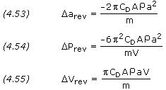
where a is the semi-major axis, P is the orbit period, and V, A and m are the satellite's velocity, area, and mass respectively. The term m/(CDA), called the ballistic coefficient,
is given as a constant for most satellites. Drag effects are strongest
for satellites with low ballistic coefficients, this is, light vehicles
with large frontal areas.
A rough estimate of a satellite's lifetime, L, due to drag can be computed from
where H is the atmospheric density scale height. A
substantially more accurate estimate (although still very approximate)
can be obtained by integrating equation (4.53), taking into account the
changes in atmospheric density with both altitude and solar activity.
Perturbations from Solar Radiation
Solar radiation pressure causes periodic variations in all of the orbital elements. The magnitude of the acceleration in m/s2 arising from solar radiation pressure is
where A is the cross-sectional area of the satellite exposed to the Sun and m
is the mass of the satellite in kilograms. For satellites below 800 km
altitude, acceleration from atmospheric drag is greater than that from
solar radiation pressure; above 800 km, acceleration from solar
radiation pressure is greater.
At some point during the lifetime of most space vehicles or
satellites, we must change one or more of the orbital elements. For
example, we may need to transfer from an initial parking orbit to the
final mission orbit, rendezvous with or intercept another spacecraft, or
correct the orbital elements to adjust for the perturbations discussed
in the previous section. Most frequently, we must change the orbit
altitude, plane, or both. To change the orbit of a space vehicle, we
have to change its velocity vector in magnitude or direction. Most
propulsion systems operate for only a short time compared to the orbital
period, thus we can treat the maneuver as an impulsive change in
velocity while the position remains fixed. For this reason, any maneuver
changing the orbit of a space vehicle must occur at a point where the
old orbit intersects the new orbit. If the orbits do not intersect, we
must use an intermediate orbit that intersects both. In this case, the
total maneuver will require at least two propulsive burns.
Orbit Altitude Changes
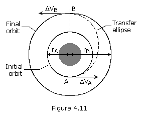
The most common type of in-plane maneuver changes the size and energy of
an orbit, usually from a low-altitude parking orbit to a
higher-altitude mission orbit such as a geosynchronous orbit. Because
the initial and final orbits do not intersect, the maneuver requires a
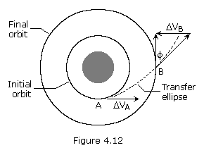
transfer orbit. Figure 4.11 represents a Hohmann transfer orbit.
In this case, the transfer orbit's ellipse is tangent to both the
initial and final orbits at the transfer orbit's perigee and apogee
respectively. The orbits are tangential, so the velocity vectors are
collinear, and the Hohmann transfer represents the most fuel-efficient
transfer between two circular, coplanar orbits. When transferring from a
smaller orbit to a larger orbit, the change in velocity is applied in
the direction of motion; when transferring from a larger orbit to a
smaller, the change of velocity is opposite to the direction of motion.
The total change in velocity required for the orbit transfer is
the sum of the velocity changes at perigee and apogee of the transfer
ellipse. Since the velocity vectors are collinear, the velocity changes
are just the differences in magnitudes of the velocities in each orbit.
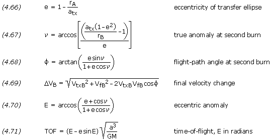
If we know the initial and final orbits, rA and rB, we can calculate the total velocity change using the following equations:
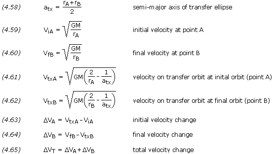
Note that equations (4.59) and (4.60) are the same as equation (4.6),
and equations (4.61) and (4.62) are the same as equation (4.45).
Another option for changing the size of an orbit is to use electric
propulsion to produce a constant low-thrust burn, which results in a spiral transfer. We can approximate the velocity change for this type of orbit transfer by
where the velocities are the circular velocities of the two orbits.
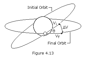
where Vi is the velocity before and after the burn, and  is the angle change required.
From equation (4.73) we see that if the angular change is equal to 60
degrees, the required change in velocity is equal to the current
velocity. Plane changes are very expensive in terms of the required
change in velocity and resulting propellant consumption. To minimize
this, we should change the plane at a point where the velocity of the
satellite is a minimum: at apogee for an elliptical orbit. In some
cases, it may even be cheaper to boost the satellite into a higher
orbit, change the orbit plane at apogee, and return the satellite to its
original orbit.
Typically, orbital transfers require changes in both the size and
the plane of the orbit, such as transferring from an inclined parking
orbit at low altitude to a zero-inclination orbit at geosynchronous
altitude. We can do this transfer in two steps: a Hohmann transfer to
change the size of the orbit and a simple plane change to make the orbit
equatorial. A more efficient method (less total change in velocity)
would be to combine the plane change with the tangential burn at apogee
of the transfer orbit. As we must change both the magnitude and
direction of the velocity vector, we can find the required change in
velocity using the law of cosines,
where Vi is the initial velocity, Vf is the final velocity, and  is the angle change required. Note that equation (4.74) is in the same form as equation (4.69).
As can be seen from equation (4.74), a small plane change can be combined with an altitude change for almost no cost in  V
or propellant. Consequently, in practice, geosynchronous transfer is
done with a small plane change at perigee and most of the plane change
at apogee.
Another option is to complete the maneuver using three burns. The
first burn is a coplanar maneuver placing the satellite into a transfer
orbit with an apogee much higher than the final orbit. When the
satellite reaches apogee of the transfer orbit, a combined plane change
maneuver is done. This places the satellite in a second transfer orbit
that is coplanar with the final orbit and has a perigee altitude equal
to the altitude of the final orbit. Finally, when the satellite reaches
perigee of the second transfer orbit, another coplanar maneuver places
the satellite into the final orbit. This three-burn maneuver may save
propellant, but the propellant savings comes at the expense of the total
time required to complete the maneuver.
When a plane change is used to modify inclination only, the
magnitude of the angle change is simply the difference between the
initial and final inclinations. In this case, the initial and final
orbits share the same ascending and descending nodes. The plane change
maneuver takes places when the space vehicle passes through one of these
two nodes.
In some instances, however, a plane change is used to alter an
orbit's longitude of ascending node in addition to the inclination. An
example might be a maneuver to correct out-of-plane errors to make the
orbits of two space vehicles coplanar in preparation for a rendezvous.
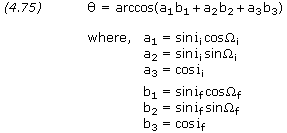
If the orbital elements of the initial and final orbits are known, the
plane change angle is determined by the vector dot product. If ii and  i are the inclination and longitude of ascending node of the initial orbit, and if and
  f are the inclination and longitude of ascending node of the final orbit, then the angle between the orbital planes,
  , is given by
The plane change maneuver takes place at one of two nodes where the
initial and final orbits intersect. The latitude and longitude of these
nodes are determined by the vector cross product. The position of one of
the two nodes is given by
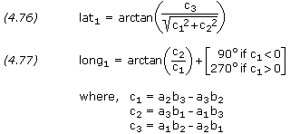
Knowing the position of one node, the second node is simply
Orbit Rendezvous
Orbital transfer becomes more complicated when the object is to
rendezvous with or intercept another object in space: both the
interceptor and the target must arrive at the rendezvous point at the
same time. This precision demands a phasing orbit to accomplish the
maneuver. A phasing orbit is any orbit that results in the
interceptor achieving the desired geometry relative to the target to
initiate a Hohmann transfer. If the initial and final orbits are
circular, coplanar, and of different sizes, then the phasing orbit is
simply the initial interceptor orbit. The interceptor remains in the
initial orbit until the relative motion between the interceptor and
target results in the desired geometry. At that point, we would inject
the interceptor into a Hohmann transfer orbit.
Launch Windows
Similar to the rendezvous problem is the launch-window problem,
or determining the appropriate time to launch from the surface of the
Earth into the desired orbital plane. Because the orbital plane is fixed
in inertial space, the launch window is the time when the launch site
on the surface of the Earth rotates through the orbital plane. The time
of the launch depends on the launch site's latitude and longitude and
the satellite orbit's inclination and longitude of ascending node.
Orbit Maintenance
Once in their mission orbits, many satellites need no additional
orbit adjustment. On the other hand, mission requirements may demand
that we maneuver the satellite to correct the orbital elements when
perturbing forces have changed them. Two particular cases of note are
satellites with repeating ground tracks and geostationary satellites.
After the mission of a satellite is complete, several options
exist, depending on the orbit. We may allow low-altitude orbits to decay
and reenter the atmosphere or use a velocity change to speed up the
process. We may also boost satellites at all altitudes into benign
orbits to reduce the probability of collision with active payloads,
especially at synchronous altitudes.
To an orbit designer, a space mission is a series of different
orbits. For example, a satellite might be released in a low-Earth
parking orbit, transferred to some mission orbit, go through a series of
resphasings or alternate mission orbits, and then move to some final
orbit at the end of its useful life. Each of these orbit changes
requires energy. The  V budget
is traditionally used to account for this energy. It sums all the
velocity changes required throughout the space mission life. In a broad
sense the
  V budget represents the cost for each mission orbit scenario.
The discussion thus far has focused on the elliptical orbit, which
will result whenever a spacecraft has insufficient velocity to escape
the gravity of its primary. There is a velocity, called the escape velocity, Vesc, such that if the spacecraft is launched with an initial velocity greater than Vesc,
it will travel away from the planet and never return. To achieve escape
velocity we must give the spacecraft enough kinetic energy to overcome
all of the negative gravitational potential energy. Thus, if m is the mass of the spacecraft, M is the mass of the planet, and r is the radial distance between the spacecraft and planet, the potential energy is -GmM /r. The kinetic energy of the spacecraft, when it is launched, is mv2/2. We thus have

which is independent of the mass of the spacecraft.
 |
 |
A space vehicle that has exceeded the escape velocity of a planet will
travel a hyperbolic path relative to the planet. The hyperbola is an
unusual and interesting conic section because it has two branches. The
arms of a hyperbola are asymptotic to two intersecting straight line
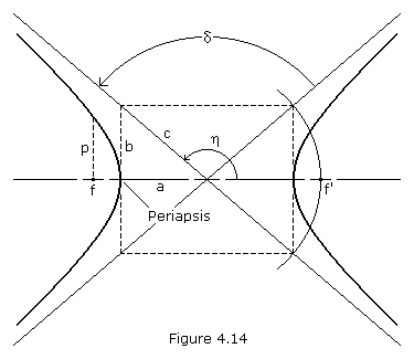
(the asymptotes). If we consider the left-hand focus, f, as the
prime focus (where the center of our gravitating body is located), then
only the left branch of the hyperbola represents the possible orbit. If,
instead, we assume a force of repulsion between our satellite and the
body located at f (such as the force between two like-charged
electric particles), then the right-hand branch represents the orbit.
The parameters a, b and c are labeled in Figure 4.14. We can see that c2 = a2+ b2 for the hyperbola. The eccentricity is,
If we let  equal the angle between the periapsis vector and the departure asymptote, i.e. the true anomaly at infinity, we have
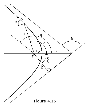
If we know the radius, r, velocity, v, and flight path angle,  ,
of a point on the orbit (see Figure 4.15), we can calculate the
eccentricity and semi-major axis using equations (4.30) and (4.32) as
previously presented. Note that the semi-major axis of a hyperbola is
negative.
The true anomaly corresponding to known valves of r, v and  can be calculated using equation (4.31), however special care must be
taken to assure the angle is placed in the correct quadrant. It may be
easier to first calculate e and a, and then calculate true anomaly using equation (4.43), rearranged as follows:
Whenever  is positive,
  should be taken as positive; whenever
  is negative,
  should be taken as negative.
The impact parameter, b, is the distance of closest
approach that would result between a spacecraft and planet if the
spacecraft trajectory was undeflected by gravity. The impact parameter
is,
Closet approach occurs at periapsis, where the radius distance, ro, is equal to
p is a geometrical constant of the conic called the parameter or semi-latus rectum, and is equal to
At any known true anomaly, the magnitude of a spacecraft's radius
vector, its flight-path angle, and its velocity can be calculated using
equations (4.43), (4.44) and (4.45).
Early we introduced the variable eccentric anomaly and its use
in deriving the time of flight in an elliptical orbit. In a similar
manner, the analytical derivation of the hyperbolic time of flight,
using the hyperbolic eccentric anomaly, F, can be derived as follows:
where,
Whenever  is positive, F should be taken as positive; whenever
  is negative, F should be taken as negative.
Hyperbolic Excess Velocity
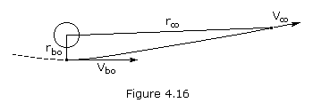
If you give a space vehicle exactly escape velocity, it will just barely
escape the gravitational field, which means that its velocity will be
approaching zero as its distance from the force center approaches
infinity. If, on the other hand, we give our vehicle more than escape
velocity at a point near Earth, we would expect the velocity at a great
distance from Earth to be approaching some finite constant value. This
residual velocity the vehicle would have left over even at infinity is
called hyperbolic excess velocity. We can calculate this velocity
from the energy equation written for two points on the hyperbolic
escape trajectory – a point near Earth called the burnout point and a point an infinite distance from Earth where the velocity will be the hyperbolic excess velocity, v∞. Solving for v∞ we obtain
Note that if v∞ = 0 (as it is on a parabolic trajectory), the burnout velocity, vbo, becomes simply the escape velocity.
It is, or course, absurd to talk about a space vehicle "reaching
infinity" and in this sense it is meaningless to talk about escaping a
gravitational field completely. It is a fact, however, that once a space
vehicle is a great distance from Earth, for all practical purposes it
has escaped. In other words, it has already slowed down to very nearly
its hyperbolic excess velocity. It is convenient to define a sphere
around every gravitational body and say that when a probe crosses the
edge of this sphere of influence it has escaped. Although it is
difficult to get agreement on exactly where the sphere of influence
should be drawn, the concept is convenient and is widely used,
especially in lunar and interplanetary trajectories. For most purposes,
the radius of the sphere of influence for a planet can be calculated as
follows:
where Dsp is the distance between the Sun and the planet, Mp is the mass of the planet, and Ms
is the mass of the Sun. Equation (4.89) is also valid for calculating a
moon's sphere of influence, where the moon is substituted for the
planet and the planet for the Sun.
Compiled, edited and written in part by Robert A. Braeunig, 1997, 2005, 2007, 2008, 2011, 2012, 2013.
http://www.braeunig.us/space/index.htm
Penulis : Drs.Simon Arnold Julian Jacob
Tidak ada komentar:
Posting Komentar
ORANMG PINTAR UNTUK TAMBAH PENGETAHUAN PASTI BACA BLOG 'ROTE PINTAR'. TERNYATA 15 NEGARA ASING JUGA SENANG MEMBACA BLOG 'ROTE PINTAR' TERIMA KASIG KEPADA SEMUA PEMBACA BLOG 'ROTE PINTAR' DIMANA SAJA, KAPAN SAJA DAN OLEG SIAPA SAJA. NAMUN SAYA MOHON MAAF KARENA DALAM BEBERAPA HALAMAN DARI TIAP JUDUL TERDAPAT SAMBUNGAN KATA YANG KURANG SEMPURNA PADA SISI PALING KANAN DARI SETIAP HALAM TIDAK BERSAMBUNG BAIK SUKU KATANYA, OLEH KARENA ADA TERDAPAT EROR DI KOMPUTER SAAT MEMASUKKAN DATANYA KE BLOG SEHINGGA SEDIKIT TERGANGGU, DAN SAYA SENDIRI BELUM BISA MENGATASI EROR TERSEBUT, SEHINGGA PARA PEMBACA HARAP MAKLUM, NAMUN DIHARAPKAN BISA DAPAT MEMAHAMI PENGERTIANNYA SECARA UTUH. SEKALI LAGI MOHON MAAF DAN TERIMA KASIH BUAT SEMUA PEMBACA BLOG ROTE PINTAR, KIRANYA DATA-DATA BARU TERUS MENAMBAH ISI BLOG ROTE PINTAR SELANJUTNYA. DARI SAYA : Drs.Simon Arnold Julian Jacob-- Alamat : Jln.Jambon I/414J- Rt.10 - Rw.03 - KRICAK - JATIMULYO - JOGJAKARTA--INDONESIA-- HP.082135680644 - Email : saj_jacob1940@yahoo.co.id.com BLOG ROTE PINTAR : sajjacob.blogspot.com TERIMA KASIH BUAT SEMUA.